| Tags: conformal-decals gamedev ksp | Jun 24, 2020 |
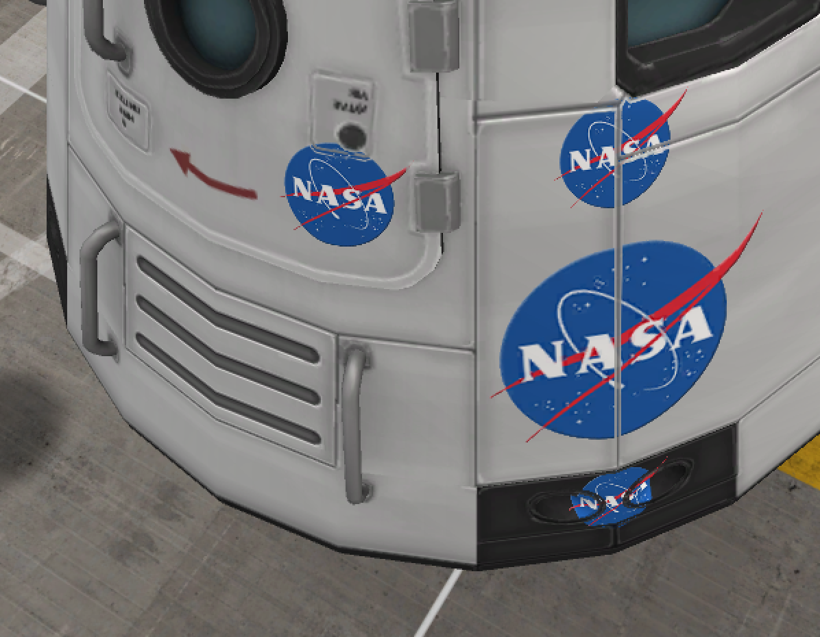
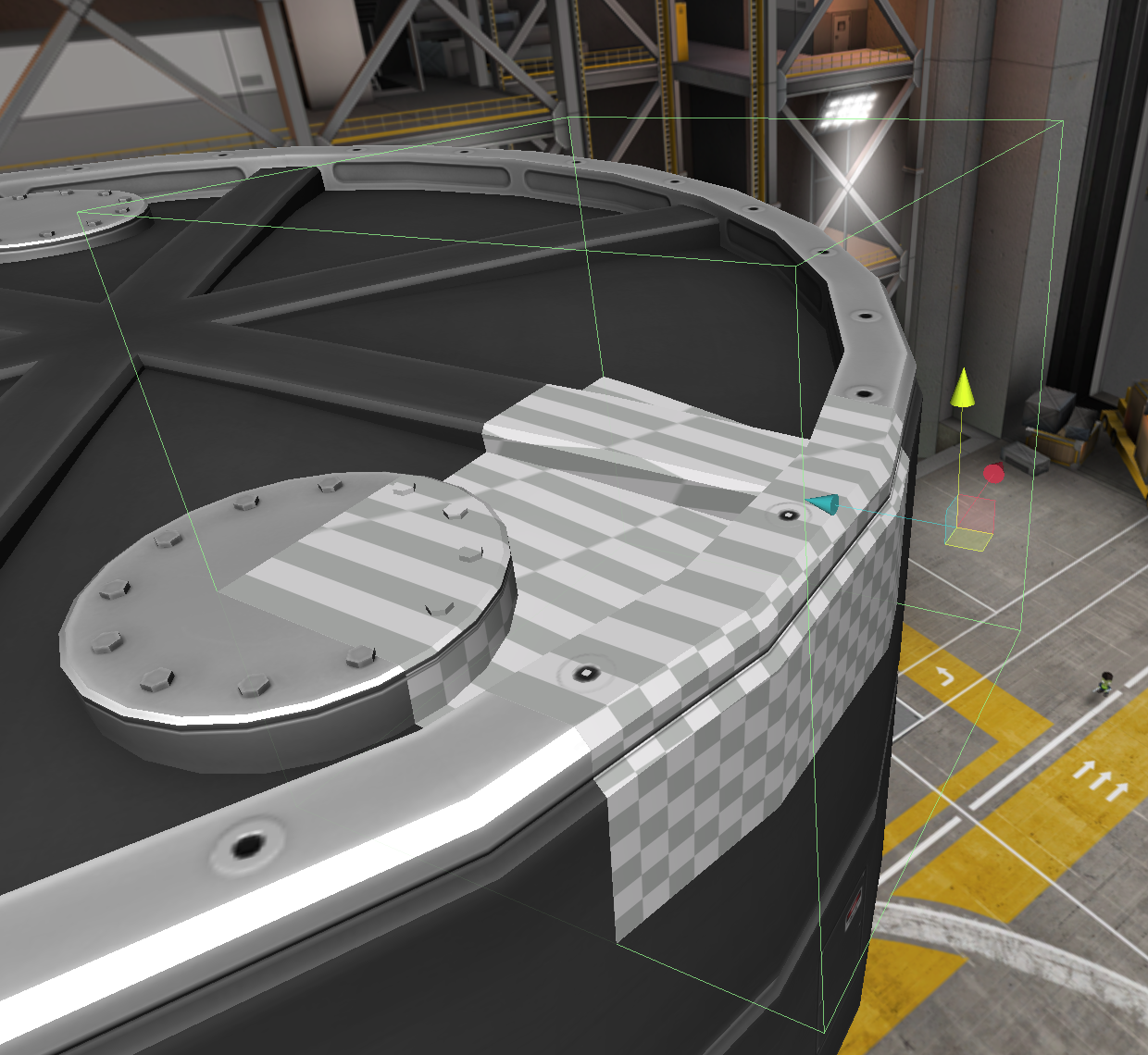
My most recent project has been Conformal Decals, a decal mod for Kerbal Space Program where the decals are projected onto the vessel, instead of being just a flat mesh on top of it.
This seemed to be an easy task, since Unity has a projector component that appeared at first glance to do exactly what I wanted. After some experimentation, however, I realized that the projector only works effectively for unlit effects, like a video projector or a shadow. Even after hacking the necessary projection math into a surface shader, information like vertex normals and tangents were missing.
Instead of giving up, I decided to write my own decal projection code. How hard could it be?
Decal Projection Math
Decal projection math is fairly straightforwards, and works exactly the same as how lighting works in forwards rendering paths. Lighting in a forwards rendering path, at least in Unity, is done by re-rendering the mesh once for every pixel light (after the initial directional light).
Decal projection works in exactly the same way. Each mesh gets rendered an additional time with a new shader and a matrix converting from vertex-space to the local space of the projector. The x and y coordinates in this space become the uv coordinates of the texture, and the z coordinate is the depth. The actual rendering is done either by adding the decal material to an additional slot on the mesh renderer component you want to project onto, or by using Graphics.DrawMesh. The generation of this matrix is fairly straightforwards with a little matrix multiplication:
1
var projectionMatrix = transform.worldToLocalMatrix * targetRenderer.localToWorldMatrix;
though since we want the projector to be in the middle of the decal’s space, we need to add an additional offset of 0.5. We can also pass in the normal vector (-Z) of the projector so our decal doesnt appear on geometry facing the wrong way (This could also be done in the shader by calculating the vertex normal in projector-space, but that means more work for the shader).
1
2
3
4
5
6
7
8
9
10
11
var orthoMatrix = Matrix4x4.identity; // orthographic projection matrix
orthoMatrix[0,3] = 0.5f; // offset x coordinate by 0.5
orthoMatrix[1,3] = 0.5f; // offset y coordinate by 0.5
var targetToProjector = transform.worldToLocalMatrix * targetRenderer.localToWorldMatrix;
var projectorToTarget = targetRenderer.worldToLocalMatrix * transform.localToWorldMatrix;

var projectionMatrix = orthoMatrix * targetToProjector;
var decalNormal = projectorToTarget.MultiplyVector(Vector3.back).normalized;

targetMaterial.SetMatrix("_ProjectionMatrix", _projectionMatrix);
targetMaterial.SetVector("_DecalNormal", decalNormal);
now in the shader you can use this matrix with the vertex position to find its location in projector-space.
1
2
// in the vertex shader
o.uv_decal = mul(_ProjectionMatrix, v.vertex);
Writing the Shader
Implementing this in a Unity surface shader works fine. You’re able to use the UVs of the mesh and the normal map of the base material to make the decal conform to the normals, or do some math to make the decal fade out with sharp normal changes, to simulate paint wearing at panel seams. The decal receives lighting automatically, and can have its opacity adjusted to fade in and out. A surface shader version of the decal shader is shown below.
1
2
3
4
5
6
7
8
9
10
11
12
13
14
15
16
17
18
19
20
21
22
23
24
25
26
27
28
29
30
31
32
33
34
35
36
37
38
39
40
41
42
43
44
45
46
47
48
49
50
51
52
53
54
55
56
57
58
59
60
61
62
Shader "ConformalDecals/Paint/Diffuse"
{
    Properties
    {
        _Decal ("Decal", 2D) = "gray" {}
        _BumpMap("Base BumpMap", 2D) = "bump" {}
        _Opacity("_Opacity", Range(0,1) ) = 1
    }

    SubShader
    {
        Tags { "Queue" = "Geometry" }
        ZWrite Off
        ZTest LEqual
        Blend SrcAlpha OneMinusSrcAlpha

        CGPROGRAM
        #pragma surface surf Lambert alpha vertex:vert
        #pragma target 4.0

        float4x4 _ProjectionMatrix;
        float4 _DecalNormal;

        sampler2D _Decal;
        sampler2D _BumpMap;
        float _Opacity;

        struct Input
        {
            float4 uv_decal : TEXCOORD0;
            float2 uv_BumpMap : TEXCOORD1;
            float4 position : SV_POSITION;
            float3 normal : NORMAL;
        };

        void vert (inout appdata_full v, out Input o) {
            o.uv_decal = mul (_ProjectionMatrix, v.vertex);
            o.uv_BumpMap = v.texcoord.xy;
            o.position = UnityObjectToClipPos(v.vertex);
            o.normal = v.normal;
        }

        void surf (Input IN, inout SurfaceOutput o)
        {
            fixed4 projUV = UNITY_PROJ_COORD(IN.decal);

            // clip fragments outside the projection area
            clip(projUV.xyz);
            clip(1-projUV.xyz);

            // clip backsides
            clip(dot(_DecalNormal, IN.normal));

            float4 color = tex2D(_Decal, projUV);

            o.Albedo = color.rgb;
            o.Normal = UnpackNormal(tex2D(_BumpMap, IN.uv_BumpMap));
            o.Alpha = _Opacity * color.a;
        }
        ENDCG
    }
}
Adding Normal Maps
Things immediately get more complicated when you want to add normal maps to your decals.
Normally when you use normal maps (pun intended), the mesh provides vertex tangent data, which tells the shader which way the normal map gets oriented, and is a vector pointing where the “u” axis of the uv map should be in 3d space. We dont have the benefit of that data for our decal projection, but since our decals are 2 dimensional, this vector is the same everywhere on the mash, and calculating it is fairly easy, just like the normal was.
1
2
3
4
5
6
7
8
9
10
11
12
13
var orthoMatrix = Matrix4x4.identity; // orthographic projection matrix
orthoMatrix[0,3] = 0.5f; // offset x coordinate by 0.5
orthoMatrix[1,3] = 0.5f; // offset y coordinate by 0.5
var targetToProjector = transform.worldToLocalMatrix * targetRenderer.localToWorldMatrix;
var projectorToTarget = targetRenderer.worldToLocalMatrix * transform.localToWorldMatrix;

var projectionMatrix = orthoMatrix * targetToProjector;
var decalNormal = projectorToTarget.MultiplyVector(Vector3.back).normalized;
var decalTangent = projectorToTarget.MultiplyVector(Vector3.right).normalized;

targetMaterial.SetMatrix("_ProjectionMatrix", _projectionMatrix);
targetMaterial.SetVector("_DecalNormal", decalNormal);
targetMaterial.SetVector("_DecalTangent", decalTangent);
But unfortunately, like a lot of Unity features that are intended to make life easier, the Surface shaders get in the way once you try to do anything interesting. The shader passes tangent data, as well as global vertex normal, binormal, and position, in a 3x4 matrix between vertex and fragment shaders. These values get completely shadowed from surface shaders, and modifying them is impossible. So we need to throw out the surface shader and write our shader from scratch.
I’m not going to go over all the things I did to rewrite the shader as a vertex/fragment shader or this article would be far too long, but I do want to make some notes that would have helped me when I was doing this, and trying to answer the question “how do I make lighting work in a vertex/fragment shader in unity”. If you want to see everything I did, the cginc file I wrote is available here.
-
Surface shaders in Unity generate a vertex/fragment shader when you compile them, which can be seen by selecting the shader and clicking “show generated code”. The resulting shader has some common vertex/fragment code that calls the
vertandsurffunctions values defined in the surface shader, which does things like applying the UV scale/offsets beforehand, and the lighting BRDF afterwards. I decided to recreate this so that as much of the calculation as possible is written in the cginc file, then the shader itself just needs to definevertandsurffunctions just like a surface shader. -
Shaders for forwards rendering in Unity have 2 passes: the base pass shades using ambient lights, emissives, and the first directional light in the scene. Then the additive pass gets called for every additional light in the scene.
-
Lighting is applied in three steps. First the
UNITY_LIGHT_ATTENUATIONmacro calculates the light attenuation value, which also includes shadows and light cookies. Then, the BRDF gets called with the surface output from thesurffunction to calculate the actual color of the pixel. Lastly, in the forward base pass only, vertex and ambient lighting gets added to the color.
How it All Could Be Improved
The biggest issue with this technique is the number of draw calls. Each mesh that a decal projects on to needs its own draw call, plus draw calls for any pixel lights. If a lot of decals are used, especially large ones which cover multiple meshes, the draw call count could get very big, very quickly. One solution would be to render all the decals on a particular mesh at once, by passing an array of projection matrices and textures into the shader, and looping over them. This would require some tweaks, like moving the projection code into the fragment shader (shaders cant interpolate an array) as well as a change to the code works where each decal is in charge of its own rendering.
Another would be to abandon forward rendering entirely, and use deferred rendering. This was not a solution for this project, since its a mod for a video game and changing the rendering path is not exactly feasable, but would work for any standalone projects. Deferred rendering would also allow for effects like modifying the normal of the underlying geometry.
Adapting the above code to other games should be straightforward, but keep in mind a lot of assumptions were made to simplify things that were only true for KSP, like not needing support for lightmaps.